- Low voltage switch cabinet
- Power distribution cabinet
- Non standard distribution box
- High voltage ring network cabinet
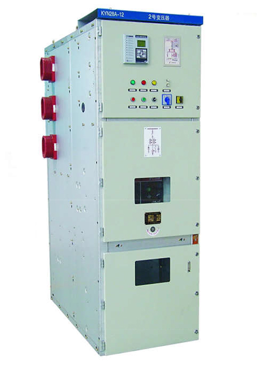
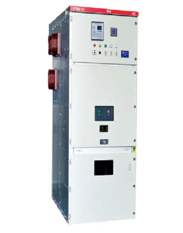
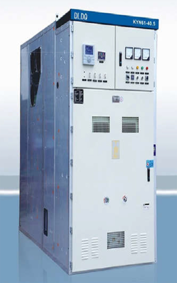
- High voltage switch cabinet
- High voltage sulfur hexafluoride switchgear
- High voltage arc suppression cabinet
- Constant pressure water supply equipment
- American box type substation
- European box type substation
- Lighting distribution box
- DC screen
- Integrated distribution box and console
- Product classification:High voltage switch cabinet
- Product specification:
- product price:¥0.00
- Order Hotline:13635605151
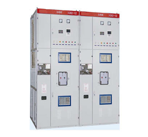
Xgn2-12 box type fixed AC metal enclosed switchgear
Describe
Xgn2-12 box type fixed AC Jinzhan enclosed switchgear (hereinafter referred to as switchgear) is designed according to the national standard GB3906 3-35kv AC metal enclosed switchgear, meets the international IEC298 standard, and meets the "five prevention" locking requirements proposed by the two ministries.
Scope of application
This product is applicable to three-phase AC single bus, double bus and single bus with bypass system with rated voltage of 3.6 ~ 12kV, 50Hz and rated current of 630-3150A, which is used for receiving and distributing electric energy. It can meet the use requirements of various types of power plants, substations (stations) and industrial and mining enterprises.
Product model and meaning

Service environmental conditions
1. Ambient temperature: upper limit + 40 ℃ lower limit - 10 ℃. The daily average value of saturated steam pressure for storage and transportation is not greater than 2.2 * 10-3mpa and the monthly average value is not greater than 1.8 * 10-3mpa at - 30 ℃;
2. Relative humidity: the daily average value is not more than 95%, and the monthly average value is not more than 90%;
3. Sea level: below 1000m (if more than 1000m, negotiate with the manufacturer for production);
4. Seismic intensity: less than 8 degrees;
5. No fire, explosion hazard, serious pollution, chemical corrosion and violent vibration
Main technical parameters
1) Main technical parameters of switchgear
| Serial number | Project | Unit | Technical parameters |
| 1 | Rated voltage (maximum working voltage) | kV | 3,6,7.2,12 |
| 2 | Rated current | A | 630-3150 |
| 3 | Rated short-circuit breaking current | kA | 16,20,31.5,40 |
| 4 | Rated short-circuit making current (peak) | kA | 40,50,80,100 |
| 5 | Rated short-circuit dynamic stability current (peak value) | kA | 40,50,80,100 |
| 6 | Rated thermal stability current | kA | 16,20,31.5,40 |
| 7 | Rated thermal stability time | S | 4 |
| 8 | Protection level | IP2X | |
| 9 | Bus system | Single bus section | |
| 10 | Operation mode | Electromagnetic type, spring energy storage type | |
| 11 | Overall dimension (W x D x H) | mm | 1100x1200x2650 ( General type) |
| 12 | weight | kg | 1000 |
2) Technical parameters of main electrical equipment in switchgear
a、Technical parameters of ZN28A-12 vacuum circuit breaker
| Serial number | Project | Unit | Technical parameters | |||
| 1 | Rated voltage (maximum working voltage) | kV | 12 | |||
| 2 | Rated current | A | 630 | 1000 | 1250, 2000 | 2500,3150 |
| 3 | Rated short-circuit breaking current | kA | 16,20 | 20,25 | 31.5 | 40 |
| 4 | Rated short circuit making current | kA | 40,50 | 50,63 | 80 | 100 |
| 5 | Rated dynamic stability current (peak) | kA | 40,50 | 50,63 | 80 | 100 |
| 6 | Rated thermal stability current | kA | 16,20 | 20,25 | 31.5 | 40 |
| 7 | Arcing time | ms | 20 | |||
| 8 | Rated operating sequence | Opening -0.3s-closing and opening-180s-closing and opening | ||||
| 9 | One minute power frequency withstand voltage (effective value) | kV | 42/48 (fracture) | |||
| 10 | Lightning impulse withstand voltage | kV | 75/85 (fracture) | |||
| 11 | Mechanical life | second | 10000 | |||
b、Technical parameters of high current disconnector
| Name | Unit | GN22-10/2000-40 | GN22-10/3150-50 | ||
| Rated voltage (maximum working voltage) | kV | 12 | |||
| Rated current | A | 2000 | 3150 | ||
| 4S thermal stability current (effective value) | kA | 40 | 50 | ||
| Dynamic stability current (peak) | kA | 100 | 125 | ||
| Rated insulation level | Lightning impulse voltage | Relatively, interphase | kV | 75 | |
| fracture | 85 | ||||
| 1 min power frequency withstand voltage | Relatively, interphase | 42 | |||
| fracture | 48 | ||||
Structural features
Xgn2-12 switch cabinet is a metal closed box structure. The cabinet frame was originally designed to be welded by angle. After development by our company, it can also be used as an example of plate bending assembly structure, which not only greatly increases the appearance, but also facilitates the organization of production and shortens the production cycle. The cabinet is divided into circuit breaker room, bus room, cable room, relay room, etc. the rooms are separated by steel plates:
1) The circuit breaker room is located at the front lower part of the cabinet, the transmission of the circuit breaker is connected by the pull rod and the operating mechanism, the upper wiring terminal of the circuit breaker is connected with the upper disconnector, the lower wiring terminal of the circuit breaker is connected with the current transformer, and the current transformer is connected with the bus bar of the lower disconnector. The circuit breaker room is also equipped with a pressure release channel. In case of internal fault arc, The gas can release the pressure through the exhaust passage:
2) The busbar room is at the upper part of the back of the cabinet. In order to reduce the height of the cabinet, the busbar is arranged in shape Supported by 7350n porcelain insulator with bending strength, the bus is connected with the upper disconnector bus, and the two adjacent bus rooms can be isolated.
3) The cable room is behind the lower part of the cabinet. The supporting insulator in the cable room can be equipped with voltage monitoring device, and the cable is fixed on the support. When the main wiring is the liaison scheme, this room is the liaison chamber The relay room is in front of the upper part of the cabinet. Various relays can be installed on the indoor installation board. There is a terminal strip support in the room, and secondary components such as indicating instruments and signal elements can be installed on the door Secondary small bus can also be arranged on the top.
4) The operating mechanism is installed at the lower position of the circuit breaker Above it is the operation and interlocking mechanism of disconnector. The switch cabinet is double-sided maintenance. The secondary components of the relay room, maintenance and operation mechanism, mechanical interlocking and transmission part and circuit breaker can be repaired in front. Repair the main bus and cable terminals at the back. There are lights in the circuit breaker room and cable room. The lower part of the front door is provided with a grounding copper bus parallel to the cabinet width direction, and its cutting surface is 4x40mm ²。
5) Mechanical interlocking: in order to prevent on-load opening and closing of disconnector, false opening and closing of circuit breaker and false entry into live interval; Prevent the grounding switch from being closed with electricity; To prevent closing with grounding knife, the switch cabinet adopts corresponding mechanical interlocking. The action principle of mechanical interlocking is as follows:
a. Power failure operation (operation maintenance)
The switch cabinet is in the working position, that is, the upper and lower disconnectors and circuit breakers are closed, the front and rear doors have been locked and are in live operation, At this time, the small handle is in the "working position". First open the circuit breaker, and then turn the small handle to "open and lock" At this time, the circuit breaker cannot be closed. Insert the operating handle into the lower isolation operating hole, pull it down from the top, pull it to the lower isolation opening position, take down the handle, and then insert it into the upper isolation operating hole, pull it down from the top to the upper isolation opening position. Then take down the operating handle, insert it into the operating hole of the grounding switch, and push it from bottom to top to make the grounding switch in the closing position. At this time, pull the small handle to the "maintenance" position. First open the front door, take out the rear key and open the back door. After the power failure operation is completed, the maintenance personnel will maintain and repair the circuit breaker room and cable room.
b. Power transmission operation (maintenance operation)
If power transmission is required after maintenance, the operation procedures are as follows:
Close the rear door, take out the key and close the front door. Pull the small handle from the "maintenance" position to the "opening and locking" position. At this time, the front door is locked and the circuit breaker cannot be closed. Insert the operating handle into the grounding switch operating bar and pull it down from top to bottom to make the grounding switch in the opening position. Take down the operating handle, insert it into the isolated operating hole and push it from bottom to top, Make the upper isolation in the closing position, take down the operating handle, insert it into the lower isolation operating hole, push it from bottom to top to make the lower isolation in the closing position, take out the operating handle, pull the small handle to the "working position", and then close the circuit breaker.